Quantcast
Channel: Mary Gannon, Author at Electrical Engineering News and Products
Viewing all 466 articles
Browse latest View live

BTB pin jumpers for maximum tolerance absorption

$
0
0

Although designed for use in conjunction with AVX’s new 2.5-mm no-wire-stop 70-9296 series STRIPT poke-home contact, the new 10-9296 Series BTB pin jumpers from AVX Corp. are drop-in compatible with competitors’ jumpers and offer a shortened insulator, a unique insulator geometry that achieves watertight connections, and the only ~38-mm pin length currently available.

AVX267-10-9296-Series-BTB-Jumper-PRThis new series of pin jumpers is designed for board-to-board (BTB) and module-to-module connections in solid-state lighting (SSL) and other low-pin-count industrial applications. When used in conjunction with the new 2.5-mm 70-9296 Series STRIPT horizontal, poke-home contact without a wire stop — which is both the first industrial poke-home connector available without an integral wire stop and, currently, the only industrial poke-home connector with a 2.5 mm profile — the new 10-9296 Series BTB pin jumpers are allowed to pass straight through the contacts, completely unrestricted, until the final, user-defined mating dimension is achieved.

Unlike traditional BTB pin jumpers — which are made to mate with traditional connectors and are thus closed on the back end, limiting the depth to which a pin can travel and restricting the amount of BTB or module-to-module mating tolerance that the jumper can absorb — the new 10-9296 Series BTB pin jumper/709296001025016 contact combination absorbs the maximum amount of component and assembly tolerances during the mating process, effectively eliminating the PCB and housing tolerance stack-up issues common to traditional connector systems in linear and coplanar applications.

The new 10-9296 Series BTB pin jumpers are rated for 9 A, 300 Vac based on contact spacing, three-cycle durability, and operating temperatures spanning -40° to 105°C, and are currently available in two different pin lengths: 26 mm to support linear BTB connections and 38.15 mm to support linear module-to-module connections in which the contacts are embedded within plastic housings. Both variants have a standard 1 mm diameter pin that is mating-compatible with competitors’ traditional 4 mm-pitch poke-home connectors, as well as the company’s own 70-9296 Series 2.5 mm STRIPT contacts — but offer two clear advantages: a shortened insulator (just 5.1 mm) and a unique insulator geometry with dual-chamfered ends that provide a watertight connection when seated within a corresponding housing cavity.

“Our new 10-9296 Series BTB pin jumpers are very user- and application-friendly, enabling variable final mating positions for maximum tolerance absorption in SSL and other low-pin-count industrial applications when combined with our new no-wire-stop 2.5 mm 70-9296 Series STRIPT poke-home contacts,” said Tom Anderson, product manager at AVX. “They are also currently the only BTB jumper on the market to offer a 38.15 mm length.”

The new 10-9296 Series BTB pin jumpers have a glass-filled Nylon PA-66 insulator approved to UL94 V-0 and lead-free, tin-over-nickel-plated brass contacts. UL approval is in progress, and is expected this month. AVX is also currently sampling a two-position version of the BTB pin jumpers, and expects to announce production inventory by May.

For more information about AVX’s new 10-9296 Series BTB jumpers, please visit http://www.avx.com/products/connectors/board-to-board/coplanarlinear/btb-jumper-10-9296/. For immediate availability, please visit Future Electronics and TTI, Inc. For all other inquiries, please visit www.avx.com, email inquiry@avx.com, like them on Facebook https://www.facebook.com/avxcorp/, follow them on Twitter https://twitter.com/avxcorp, call 864-967-2150, or write to One AVX Boulevard, Fountain Inn, S.C. 29644.

About AVX

AVX Corporation is a leading international manufacturer and supplier of advanced electronic components, interconnect, sensing, control, and antenna solutions with 29 manufacturing facilities in 16 countries around the world. AVX offers a broad range of devices including capacitors, resistors, filters, couplers, sensors, controls, circuit protection devices, connectors, and antennas. The company is publicly traded on the New York Stock Exchange (NYSE:AVX).

For more information, contact:

Tom Anderson

Connector Product Manager, AVX

843-241-2179

tom.anderson@avx.com

Christina Sandidge

Public Relations Specialist, BtB Marketing

919-872-8172

christina.sandidge@btbmarketing.com

If you would rather not receive future communications from BtB Marketing Communications, let us know by clicking here.
BtB Marketing Communications, 900 Ridgefield Dr. Suite 135, Raleigh, NC 27609 United States

AVX267 10-9296 Series BTB Jumper PR.jpg

The post BTB pin jumpers for maximum tolerance absorption appeared first on EE World Online | A network of resources for engineers.


AutomationDirect offers customer specified cut-to-length cables

$
0
0

Bulk multi-conductor industrial automation cable from AutomationDirect is now available in customer specified lengths in one-foot increments from 20 to 5,000 ft. Cut-to-length cable eliminates waste and lowers cost (only as much cable as required is purchased).

AutomationDirect-cut-to-length-cable-5x7With a low minimum cut length of 20 feet, the price per foot per cable type is the same regardless of length ordered. There are no cut charges and on orders over $49, there are no shipping charges. Cable is cut to length at AutomationDirect’s own UL Certified respooling facility and is available for same day shipping if ordered by 6:00pm ET.

Cut-to-length multi-conductor cable types include flexible portable cord, RS232/ RS422/ RS485 data cable, flexible control (tray) cable, instrumentation cable, continuous flexing control cable, and continuous flexing industrial Ethernet cable.

Cut-to-length cables start at $0.30 per foot (20-foot minimum), have a one-year warranty and are backed by AutomationDirect’s standard 30-day return policy.

AutomationDirect
www.automationdirect.com/cut-to-length-cable

The post AutomationDirect offers customer specified cut-to-length cables appeared first on EE World Online | A network of resources for engineers.

Why do connectors fail?

$
0
0

Ideally, your connectors perform to their rated lifecycles. If you install a connector rated for 10,000 mating cycles, you expect it to go that distance. But if you’ve ever had a cell phone charger stop working correctly, you know that’s not always the case. And for industrial machinery, improper designs and other factors can cause connectors to fail prematurely, which can cause costly machine damage. Here’s a look at some common causes of failure and how to prevent them.

Aircraft_Connector

Failure is not an option in aircraft connectors. Illustration courtesy of Cleaver Brinkerhoff.

Wear and tear — Like the example above, repeated connection and disconnection of a connector can cause the metal on the contacts to wear and corrode if exposed to water, dust, dirt and other harsh elements. As a result, the mating pins may not properly engage when inserted into the connector shell. Always choose connectors rated for the required mating cycles you will need.

Improper selection — Environments where there may be moisture ingress require special connectors. If a standard connector is used in place of one with an IP68 or IP69 rating or a hermetic design, water can cause the connector to fail. Choosing an undersized connector can also reduce efficiency, thus making the connector work harder to keep up with demand. This will decrease connector life.

Extreme temperatures — If connectors are not rated for extremely high or low temperatures, they will eventually fail. If not rated for high temperatures, the insulation fails and conductivity will also spike. If operated at continued high temperatures, these spikes will add to the temperature elevation, which can cause corrosion and eventually, reduced contact force. This can impact the electrical signal traveling through the connector and cable assembly, which in turn can create an open circuit.

While cold temperatures do not impact connectors as harshly as hot temperatures do, low-temperature designs should be considered if you know your application will require them. Exposure to continued low-temperatures can cause tin-plated connector materials to soften, which in turn increases contact resistance. In addition, cold temperatures can impact other parts of the connector, like making plastic shells go brittle.

Improper design and installation — If an application will experience shock, vibration and other damaging motions, it is important to find secure designs that create a strong latch. If not securely mounted, the connector contacts, the mating shells and even the cable could suffer damage. In addition, connector and cable assemblies must have proper strain relief and installation routing — using guided troughs, cable carriers and cable glands help to ensure rated assembly life.

The post Why do connectors fail? appeared first on EE World Online | A network of resources for engineers.

New configurator tool allows users to custom design industrial connectors

$
0
0

HARTING has developed its Han configurator tool for industrial connectors that enables designers to quickly obtain all decision-relevant data for an interface they need. Users need only enter three parameters — the number of contacts, required voltage, and current strength — to obtain a visual presentation of an initial potential solution. The solution can then be accepted or further refined. Equally adequate alternatives can be obtained with a just few mouse clicks.

configurator tool
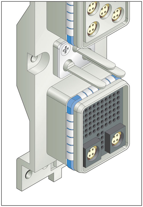
There are two ways to work with the configurator:

  • With selection support: input the number of contacts, voltage and current strength, and the configurator develops suggestions for suitable interfaces.
  • Without selection support: individuals familiar with the Han portfolio have the option to construct the interface in the configurator on their own, e.g. select housing top/bottom, specify pin/socket inserts, etc.

Regardless of which option the user chooses, the Han configurator makes it easy to master the topic of “connectors” despite increasingly complex requirements and generally high product diversification. The most important aid is clarity, which is achieved by employing a 3D model to continuously visualize the state of the user’s component selection. In addition to the technical data that’s entered, the configurator factors in previous decisions. As a result, parts that don’t match with a previous selection are no longer displayed as an option — making it impossible to combine components incorrectly.

The new configurator also makes collaboration easier. Interface solutions which have been developed can be saved, shared and called up at any time. “The configurator enables a new kind of cooperation between manufacturer and supplier,” said Andreas Wedel, Head of the Technical Competence Center at HARTING Electric.

The HARTING Technology Group 
www.HARTING.com

The post New configurator tool allows users to custom design industrial connectors appeared first on EE World Online | A network of resources for engineers.

Hybrid active optical cable assembly supports up to 12.5 Gbps and 3.3 V

$
0
0

Hirose has designed an intrafacility fiber cable (IFC) assembly system that supports bidirection optical transmission of 6.25 Gbps and unidirection up to 12.5 Gbps (6.25 Gbps x 2ch). The high-speed BF4-IFC series cable assembly integrates the BF4M series active optical connector into a rugged circular shell with a superior push-pull design for quick and easy mating/unmating operation. The high-speed BF4-IFC series cable assembly system features built-in E/O on the Tx (transmit) end and an O/E on the Rx (receiver) end. Simplifying designs and increasing ease of use, the hybrid active optical cable system also delivers power up to 3.3V.

Hirose BF4-IFC PR imageThe innovative BF4-IFC active optical connector and cable assembly system enables high-speed data transmission at cable lengths of more than 50 m. The user-friendly optical cable system features an innovative internal wiring system that offers all the benefits of fiber optic signaling including high signal quality, low power consumption (less than 250 mW), and excellent EMI noise prevention. Reducing system size and cost, the hybrid BF4-IFC active optical cable assembly streamlines wiring by integrating four electrical wires for power delivery and signal transmission control into one cable interface.

The BF4-IFC active optical cable plugs into a reliable panel mount receptacle that solders to the PCB.

Combining high strength with excellent flexing properties, the BF4-IFC cable is an ideal solution for any application that requires long reach, high speed and limited wiring space including broadcasting equipment, data centers, medical equipment, FA cameras, security cameras, and more.

“The BF4-IFC connector and cable assembly simplifies design and installation by providing both high-speed optical data transmission and power delivery through a single hybrid optical fiber and electrical cable system. The advanced design ensures high speed, low power, and low noise operation,” said Bill Kysiak, Product Marketing Manager for Hirose Electric USA.

Hirose
www.hirose.com/us


The post Hybrid active optical cable assembly supports up to 12.5 Gbps and 3.3 V appeared first on EE World Online | A network of resources for engineers.

Molex acquires FPGA-computing system provider BittWare

$
0
0

Molex has acquired BittWare Inc., a global provider of computing systems featuring field-programmable gate arrays (FPGAs) deployed in data center compute and network packet processing applications.

“Among the foremost FPGA computing platform developers, BittWare brings an impressive breadth of board-level computing technologies, integrated systems and software expertise,” said Tim Ruff, senior vice president of Molex.

According to Mark Gilliam, president of Interconnect Systems International, a Molex company, “The acquisition expands on the capabilities of Molex and its subsidiary Nallatech to address the rising demand for FPGA-based high-performance compute and network processing solutions.”

Headquartered in Concord, N.H., BittWare provides solutions based on FPGA technology from Intel (formerly Altera) and Xilinx. Many of the world’s leading companies use BittWare FPGA solutions to provide the processing power for demanding applications in compute and data center, military and aerospace, government, instrumentation and test, financial services, broadcast and video.

“FPGA-based platforms have become a strategically important driver of machine learning, artificial intelligence, cybersecurity, network acceleration, IoT, and other megatrends. As a Molex subsidiary, now working with Nallatech, I believe we will have the critical mass to bring new resources, better processes, and economies of scale to our valued customers and this rapidly growing industry as a whole,” said Jeff Milrod, president and CEO of BittWare.

BittWare commercial products turn the latest FPGA device features into reliable board-level solutions, suitable for both development and deployment in integrated servers. The company serves original equipment manufacture (OEM) customers, who value the decades of engineering experience BittWare brings to designing custom solutions and manufacturing them at scale with partners such as Benchmark Electronics. BittWare products are supported with extensive tools, FPGA IP, and in-house technical support staff.


Molex
www.molex.com

The post Molex acquires FPGA-computing system provider BittWare appeared first on EE World Online | A network of resources for engineers.

Solderless and direct plug-in connectors from Würth Elektronik

$
0
0

Würth Elektronik eiSos has introduced its new “REDFIT IDC SKEDD WR-WST connectors” product family: solderless, space-saving and multi-pluggable connectors for signal transmission. The electronics and electromechanical components manufacturer is using the patented SKEDD technology from its sister company Würth Elektronik ICS for this innovative product. REDFIT IDC is available in 4- to 20-pin versions and is suitable for permanent use on PCBs as well as for temporary connections for programming and debugging purposes.

Wurth-Elektronik-Redfitt-IDC-SKEDD-CONNECTORSREDFIT IDC is a solderless reversible direct plug-in connector with SKEDD technology. It can be manually mounted on the plated-through holes of the PCB, which eliminates the need for extra sockets and any related soldering processes. The REDFIT IDC SKEDD also requires no mating plug, therefore saving on yet another component and reducing assembly and process costs.

For miniaturized components in particular, the less space required and the lower the height needed for any pin headers and other connector components, the better. REDFIT IDC SKEDD connectors only take up room for the connector itself on the PCB – there is no need for extra space above the circuit board.

The SKEDD connector is attached to the ribbon cable via insulation displacement technology. The plastic guides on the underside of the housing are longer than the contacts, thus preventing short circuits on the board underneath. Different size thicknesses of the guiding pins provide reverse polarity protection during the simple, (and tool-free), process of plugging and unplugging of the SKEDD connector. Depending on the application, between 10 and 25 mating cycles are specified.

The plastic housing of REDFIT IDC SKEDD WR-WST connector family of products is made of halogen-free LCP (liquid crystal polymers) of flammability class UL94 V0. The specified operating temperature ranges from -25°C to 105°C. The contact material, a copper alloy, is gold-plated on the SKEDD site and tin-plated on the IDC. The SKEDD contacts on the dual row plug connector are offset with a 2.54 mm pitch. On the cable side, the AWG 28 ribbon cable is connected with a 1.27 mm pitch. Further technical features include a rated current of 1.0 A per pin, an operating voltage of 100 V, isolation resistance of >1,000 MΩ, voltage stability of 500 Vac/min, and contact resistance of max. 10 mΩ.

“The robust REDFIT IDC SKEDD connectors are ideal for all applications that require a stable and space-saving signal connection or where a detachable connector requires tool-free maintenance. A good example is that of a debugger/microcontroller scenario. Previously, whenever firmware was installed after assembly, an extra socket had to be soldered to the board for that purpose – an additional component that was often used only one single time. Our new SKEDD connectors save on materials, space and costs,” said Daniel Kübler, Business Development Manager at Würth Elektronik eiSos.

The REDFIT IDC SKEDD connector is immediately available from stock with 4, 6, 8, 10, 12, 14, 16, 18 or 20 pins, and in any quantities. Free samples can be requested.

Würth Elektronik eiSos GmbH & Co. KG
www.we-online.com

The post Solderless and direct plug-in connectors from Würth Elektronik appeared first on EE World Online | A network of resources for engineers.

BTB pin jumper series for maximum tolerance absorption

$
0
0

BTB pin jumperAVX Corp. has extended its new series of BTB pin jumper series and module-to-module connections in solid-state lighting (SSL) and other low-pin-count industrial applications with a new two-position pin jumper. When used in conjunction with the new 2.5 mm 70-9296 Series STRIPT horizontal, poke-home contact without a wire stop — which is both the first industrial poke-home connector available without an integral wire stop and, currently, the only industrial poke-home connector with a 2.5-mm profile — the new one- and two-position 10-9296 Series BTB pin jumpers are allowed to pass straight through the contacts, completely unrestricted, until the final, user-defined mating dimension is achieved.

Unlike traditional BTB pin jumpers — which are made to mate with traditional connectors and are thus closed on the back end, limiting the depth to which a pin can travel and restricting the amount of BTB or module-to-module mating tolerance that the jumper can absorb — the new 10-9296 Series BTB pin jumper/709296001025016 contact combination absorbs the maximum amount of component and assembly tolerances during the mating process, effectively eliminating the PCB and housing tolerance stack-up issues common to traditional connector systems in linear and coplanar applications.

The new 10-9296 Series BTB pin jumpers are rated for 9 A, 300 Vac based on contact spacing, three-cycle durability, and operating temperatures spanning –40° to 105°C, and are currently available in one- and two-position versions in two different pin lengths. The 26 mm pins are designed to support linear BTB connections, while the currently unique-to-market 38.15 mm pins are designed to support linear module-to-module connections in which the contacts are embedded within plastic housings. All four variants have a standard 1-mm diameter pin that is mating-compatible with competitors’ traditional 4-mm-pitch poke-home connectors, as well as the company’s own 70-9296 Series 2.5 mm STRIPT contacts — but offer two clear advantages: a shortened insulator (just 5.1 mm) and a unique insulator geometry with dual-chamfered ends that provide a watertight connection when seated within a corresponding housing cavity.

“We tooled our one-position 10-9296 series pin jumper for a customer and then released it to market in April to provide engineers working on SSL and other low-pin-count industrial applications with user-friendly solutions for achieving variable final mating positions for maximum tolerance absorption, especially when combined with our new no-wire-stop 2.5-mm 70-9296 Series STRIPT poke-home contacts,” said Tom Anderson, connector product manager at AVX. “We tooled the new two-position 10-9296 Series pin jumper as a standalone product to help resolve customer frustrations regarding the unstable delivery schedule of similar products from competitors. However, AVX didn’t just duplicate the current products on the market. We re-engineered our product to make it cleaner than competitors’ offerings, which are often built as a larger version and then broken or cut to length, leaves burrs or vestiges behind. All of the customers who have sampled our new two-position BTB pin jumper have commented on the sleekness and cleanliness of our product.”

The new 10-9296 Series BTB pin jumpers have a glass-filled Nylon PA-66 insulator approved to UL94 V-0 and lead-free, tin-over-nickel-plated brass contacts. UL approval is in progress, and is expected in shortly.

AVX Corp.
www.avx.com

The post BTB pin jumper series for maximum tolerance absorption appeared first on EE World Online | A network of resources for engineers.


What are hermetic connectors?

$
0
0

Hermetic connectors are designed to prevent ingress of air, gases and other liquids into the vacuum-sealed connector in extremely harsh environments. In testing, these connectors should show no detectable gas or fluid leakage.

Hermetically sealed connectors from Ametek

Hermetically sealed connectors from Ametek

They should be able to withstand high pressures of 10,000 psi or more, ensuring a stable pressure differential on both sides of the assembly. Ideally, hermetic seals must withstand low to high pressures and altitudes seen in military applications, offshore applications to extreme depths, and commercial and industrial operations.

Pave Technology's hermetic connectors and assemblies

Pave Technology’s hermetic connector assemblies

Most hermetic connectors are glass sealed because the glass creates a rigid form for the metal shell to compress against. This compression creates the hermetic seal. The glass is bonded to and supports the contacts.

They also must withstand extreme temperature variations, from approximately -100° to 200°C and resist damaging vibration.

These connectors can use stranded or solid plated copper conductors, insulated conductors, copper, brass or Nickel iron pin contacts and fiber optic cables. They can be designed into a helium gas-tight bulkhead or harness assembly with connectors preinstalled.

Because they are manufactured to operate in harsh environments, most hermetic connectors are made of durable metals, including stainless steel, glass and Nickel iron. However, while glass is the most effective insulating material it can add unnecessary weight in some applications. Here, epoxy seals are used. Additionally, aluminum alloy shells can cut the weight in half.

The post What are hermetic connectors? appeared first on EE World Online | A network of resources for engineers.

TE Connectivity partners with Annapolis Micro Systems on FPGA boards

$
0
0

TE Connectivity (TE) has partnered with Annapolis Micro Systems, an FPGA board and systems supplier, on the release of three new high-performance FPGA boards that feature TE’s NanoRF module. The half-size NanoRF is designed to fit into the VITA 67.3 form factor and supports 70 GHz bandwidth, with more than double the RF contact density of existing VITA 67 solutions.

The three new OpenVPX boards from Annapolis Micro Systems include:

  • WILDSTAR 3XB0 3U OpenVPX FPGA Processor
  • WILDSTAR 3XB1 3U OpenVPX FPGA Processor
  • WILDSTAR 6XB2 6U OpenVPX FPGA Processor

TE Connectivity Anapolis Micro Systems FPGA boardsEliminating the need for front panel coaxial cables, the NanoRF design leverages the alignment features of optical (VITA 66) modules. A floating insert on the backplane pre-aligns the RF contact array before the contacts start to engage. This rugged precision alignment is critical in blindmate plug-in architecture, which requires high reliability under extreme conditions.

“The NanoRF gives us super high density out the backplane in a really tight package,” said Noah Donaldson, Annapolis Micro Systems Chief Technology Officer. “This breakthrough connectivity allows us to utilize the full performance capability of these super-powered FPGA boards and our high-channel-count I/O cards.”

The cutting-edge COTS boards integrate up to two Xilinx Virtex UltraScale+ FPGAs and a Xilinx Zynq UltraScale+ MPSoC motherboard controller. Each board also has one (3U) or two (6U) WILD FMC+ (WFMC+) next generation I/O site(s), for dense, high-bandwidth ADCs and/or DACs.

According to Mike Walmsley, TE Global Product Manager, “These Annapolis Microsystems OpenVPX applications are a perfect illustration of the rugged RF density that can be achieved for next generation embedded systems. TE is pursuing the NanoRF modules as an industry standard VITA 67.3 solution to enable unprecedented bandwidth in a smaller package.”

TE gave Annapolis early access to the NanoRF; widespread launch will take place in August.

The backplane contacts in the NanoRF modules are float mounted, assuring that the coax interface is fully bottomed in VPX backplane applications, and maintains excellent isolation and VSWR in rugged environments. Multiple position options from 8 to 18 positions are offered in half and full-size modules, and custom module configurations are possible utilizing the same NanoRF interface.

The three FPGA processors supplement Annapolis’ WILD™ EcoSystem. The EcoSystem is an interoperable portfolio of rugged high-performance OpenVPX and PCIe COTS boards and systems that are used for challenging data acquisition, digital signal processing, and data storage applications.

The FPGA boards are designed for advanced High Performance Computing (HPC) and Electronic Warfare (EW) applications, including DRFM, beamforming, sensor processing, wireless communication, and radar signal processing.

TE Connectivity 
www.te.com

The post TE Connectivity partners with Annapolis Micro Systems on FPGA boards appeared first on EE World Online | A network of resources for engineers.

Parallel board-to-board connectors for low-profile mating

$
0
0

Mill-Max Mfg. Corp. has introduced new Horizontal SMT (HSMT) headers and sockets suited for low-profile parallel board-to-board or board-to-component mating. The removable plastic cap provides the convenience of a traditional connector and once removed delivers an interconnect system with a minimal surface mount profile.

Mill-Max parallel board-to-board connectorsThese new sockets, 835-43-0XX-40-030001, and headers, 328-10-1XX-40-020001 are an excellent choice for applications where vertical board stacking is not an option, such as in LED lighting systems which often employ daisy-chained PCBs to minimize overall package height. This new series of HSMT connectors have an above-board profile of 0.096 in. (2.44 mm) with the cap in place and just 0.072 in. (1.83 mm) with the cap removed. The cap serves multiple functions: it maintains accurate pin-to-pin spacing, enables group placement of low profile SMT pins and receptacles and provides a flat pick and place surface for efficient automated assembly. After soldering, it may be easily removed to achieve a minimal profile.

The connectors are single row with 0.100 in. (2.54 mm) pin spacing and are available in 2-10 positions. All are packaged on tape and reel (1,450 parts per 13 in. reel) per EIA-481 standards; tape widths vary with pin count. The cap material is high-temperature Nylon with an HDT of 260° C to withstand most soldering processes.

Each pin and receptacle is precision turned from brass alloy. The receptacle has a highly reliable 4-finger, beryllium copper contact and accepts leads ranging from 0.015 – 0.025 in. (0.38 – 0.635 mm). The standard plating for the sockets is tin on the shell and gold on the internal contact providing optimal interconnect reliability. The header pins come standard with gold plating.

Mill-Max Manufacturing
www.mill-max.com/PR686

The post Parallel board-to-board connectors for low-profile mating appeared first on EE World Online | A network of resources for engineers.

Next-generation free height connectors for 32 Gbps and higher speeds

$
0
0

TE Connectivity has introduced its next-generation 0.8-mm free height board-to-board connectors, which achieve unrivaled speeds of 32 Gbps and higher. These high-speed, mid-density mezzanine solutions deliver an excellent price-to-performance ratio and are 56 Gbps PAM-4 and PCIe Gen 5 capable for future upgrades.

TE-Connectivity-25G-Free-Height-editThere is a growing need for mezzanine connectors capable of delivering 25 Gbps and higher signal, necessitating the upgrade of existing 10 Gbps mezzanine connectors in the coming years. Anticipating the need for even higher speeds over the next five years as the market moves toward PCIe Gen 5 architectures, TE has developed free height connectors capable of 32 Gbps and higher speeds that can offer significant system cost savings in adopting 32 Gbps technologies for high-volume server and storage applications. The new free height connectors also deliver higher reliability through a stronger plug/receptacle mechanical design, maintaining the same performance when de-mated up to 0.5mm. In addition, modular tooling enables 1mm stack height increments and flexible pin counts.

TE Connectivity Ltd.
www.te.com

The post Next-generation free height connectors for 32 Gbps and higher speeds appeared first on EE World Online | A network of resources for engineers.

New FPC/FFC connectors prevent misalignment

$
0
0

Kyocera Corp. announced that its 0.5 mm-pitch flexible printed circuit (FPC) and flat flexible cable (FFC) electronic connectors are available with improved quality assurance (QA) checks – both visual and automated optical inspections (AOI) – to prevent misalignment. Kyocera’s new 6892 Series connectors also feature an operating range from –40 to 125℃ and high-speed transmission making them ideal for automobile applications. The new connectors are available globally in this month.

Kyocera-6892_Series_ConnectorWith the increasing use of electronics in vehicles such as Advanced Driver Assistance System (ADAS) and connected cars, the performance of automotive electronics is improving. This trend pushes the demand for connectors offering high-speed transmission capability to be used for in-vehicle infotainment, vehicle-mounted cameras, and radars, as well as reliability and optimal performance under harsh environments such as vibration and extreme temperatures.

Kyocera aims to contribute to the evolution of the automotive industry by expanding its lineup with FPC/FFC connectors featuring heat resistance and high-speed transmission capability to meet the industry’s growing technology requirements.

Kyocera’s new 0.5 mm-pitch FPC/FFC connectors correspond to the high-speed transmission interfaces of V-by-One HS and CalDriCon. The V-by-One HS reaches up to 3.75 Gbps maximum speed.

Main features include:

  • Visual checks and AOI to prevent misalignment — The 6892 Series’ design enables users to easily confirm quality assurance by both visual checks and AOI. Windows on the actuator enable users to confirm insertion status and the actuator is unable to close until the FPC/FFC is in the correct position, preventing misalignment. The windows on both sides of the actuator allow a visual check for proper insertion.
  • Visual check — Actuator will not close until correctly inserting FPC/FFC.
  • Supports automated assembly line to enhance operation efficiency — The 6892 Series is suitable for robotic insertion and contributes to improving the operating efficiency in the manufacturing process.
  • Excellent design to protect FPC/FFC — The design of the new connector makes the center tip of an insulator go into windows of an actuator, which makes it difficult to break the locking section even when forcedly pulling the FPC/FFC.
  • Wide operating range from –40 to 125℃ — This range is ideal for the extreme temperatures required for automotive and industrial applications. The commodity type for consumer equipment applications with a heat resistance up to 105℃ will also be available.
  • Accommodates shielded FFCs with grand terminals — The 6892 Series accommodates shielded FFCs with grand terminals that optimize high-frequency by impedance matching and reduce the effect of noise.

Kyocera 
www.kyocera-connector.com/en

The post New FPC/FFC connectors prevent misalignment appeared first on EE World Online | A network of resources for engineers.

Smart photoelectric sensor is easily configured via IO-Link

$
0
0

Generating, transporting and processing information are central tasks in the Industry 4.0 environment. The basis for all this information is intelligent sensors which provide the required input. With its new BOS 21M ADCAP, Balluff has created a smart photoelectric sensor.

21M ADCAPThe versatile all-rounder uses red light and lets you choose from among four sensor modes: background suppression, energetic diffuse, retroreflective or through-beam sensor. All the sensor functions can be configured over IO-Link while the system is running so that a remote teach-in can be initiated by the controller.

In addition, the sensor detects actual operating conditions, collects and processes information and provides far more data than just the switching signal over IO-Link. Detection signals are prepared and pre-processed in the sensor. This relieves the burden on the system controller and reduces data volume on the Fieldbus systems.

Comprehensive, smart diagnostics functions provide important information such as life expectancy, operating hours and function reserve. Increasing amount dirt deposits, sensor misalignment, setting errors or other irregularities can then be reliably detected early by monitoring the emissivity values as a measure of the sensor signal quality. Finally, when it comes to operating security this intelligent sensor offers even more. The BOS 21M ADCAP is the first to optically monitor the output of the emitter LED directly and to determine the “stress level” by means of the sensor interior temperature and the supply voltage.

Balluff
www.balluff.com

The post Smart photoelectric sensor is easily configured via IO-Link appeared first on EE World Online | A network of resources for engineers.

How do canted coil springs provide EMI/RFI shielding?

$
0
0

Canted coil springs shield sensitive electronics from the harmful effects of EMI/RFI. Featuring independent coils that serve as multiple contact points for optimal conductivity and/or grounding, these springs ensure consistent, reliable connection with mating surfaces, even under shock and vibration. These springs feature precisely engineered coil angles.

Bal Seal canted coil spring offers EMI/RFI shielding in cables

Bal Seal canted coil spring offers EMI/RFI shielding in cables

Canted coil springs are ideal for use in high-frequency, small-package applications. Because they can be used to shield and mechanically fasten with precisely controllable insertion and removal forces, they reduce system weight, size and complexity.

Common applications include cabling, coaxial and electrical connectors, connectors, connect/disconnect assemblies, electronic enclosures, waveguide flanges, and more.

In addition to shielding, they hold, latch and lock. They feature customizable mechanical forces, and their electrical properties can be “tuned” to meet specific impedance requirements.

Offering unique deflection and force behavior upon compression, the springs are available in a variety of configurations and coil shapes, and with various options:

  • As closed rings or straight lengths
  • In a variety of sizes
  • In a variety of materials, including copper alloy and stainless steel
  • With gold, silver, nickel or tin platings for optimal conductivity, galvanic compatibility and corrosion resistance

Supplying near constant force over a large compression range, these springs provide consistent shielding despite surface irregularities and tolerance variations.

Additional features of canted coil springs include:

  • They act as a latching component, providing an audible click that confirms secure connection with no threading and easy removal
  • Conductive/shielding properties provide protection against cross-talk, and interference from other devices in use

Key benefits of canted coil springs include:

  • 3-in-1 functionality: Shielding, conducting and connecting while reducing weight, size and complexity of designs
  • Resistance to compression set for longer service life (as compared with elastomers and fingerstock)
  • Individual coils exert near constant force
  • Compensation for misalignment and surface irregularities
  • Ability to enable tool-less modular designs
  • Easy maintenance, part-switching

Information courtesy of Bal-Seal Engineering

The post How do canted coil springs provide EMI/RFI shielding? appeared first on EE World Online | A network of resources for engineers.


ix industrial connectors meet the need for smaller footprints

$
0
0

Contributed by Jonas Diekmann, Technical Editor for HARTING

Industrial devices are steadily getting smaller, requiring smaller, yet stronger interfaces. For Cat6A Industrial Ethernet applications, HARTING offers users ix Industrial connectors in A-encoding. To be able to supply even more applications, in the future the small interface will also be available in 10-pole signal design – ix Industrial Signal in B-encoding.

ix industrial connectors

HARTING’S ix Industrial connectors

Industrial devices are getting smaller and more refined. At the same time interfaces for data and power, which have been on the market for decades, are often used. Quality guarantees are given freely. In many applications, however, RJ45 and M12 connectors are now by far the largest components within a device and therefore require an unnecessarily large amount of space. At the same time, stability remains a constant problem, especially with RJ45. Broken ratchet levers are not uncommon. With the ix Industrial, HARTING offers a significantly smaller and stronger interface for industrial Ethernet.

Thanks to norms and standardization, HARTING expanded the development of this miniaturized interface. Therefore, at the 2018 Hanover Fair, the ix Industrial connector was presented in a new housing design with improved haptic qualities that make handling significantly safer and easier. And unlike the Gigabit version, with its new Type B version with 10 contacts for signals and serial BUS systems, all 10 contacts are used for signal transmission and not used as shielding elements of separate contact pairs. Externally, the new B-encoding can hardly be distinguished from the Gigabit version. Only the plug profile hints at a different use case. The different encodings also ensure that an Ethernet interface is not inadvertently connected to a signal interface, which would lead to malfunctions.

Harting ix Industrial Type A encoding

Type A encoding

The other benefits remain unchanged. Minimum size and shape are identical and 70 % smaller on the socket-side than with conventional RJ45. This allows device manufacturers to produce a smaller device or to fit it with more interfaces for the same size. This option meets ever increasing data rates and wider use of Ethernet. To equip the interface for future industrial applications, it was not only necessary to reduce the installation space, but also to increase stability at the same time. The ix interface is intended to usher in a future standard, which can replace the often sensitive RJ45 solutions with plastic locking levers. This stability is ensured by the 5 THR pins of the socket in the printed circuit board and metal hooks in the plug. A cable clamp firmly attached to the connector housing ensures the corresponding strain relief of the connection.

The new type B-encoding is also standardized in accordance with IEC 61076-3-124 and offers users investment security as well as all the properties associated robustness and reliability. This means that shock and vibration cannot affect the signal version. The robust locking system featuring metal hooks ensures a reliable connection and a shield housing with a simplified structure reduces the number of individual parts. This aspect plays a special role in the assembly process. An audible click signals secure locking, increasing user-friendliness and giving fast and simple feedback.

HARTING ix Industrial Type B encoding

HARTING ix Industrial Type B encoding

To simplify the assembly of the connectors, in the future both ix Industrial versions will also be available as IDC (IDC = Insulation Displacement Contact). This simplifies and speeds up the connection in contrast to the permanently soldered version and spares the user from having to perform the soldering process. In addition, both versions are available as ready-made cable assemblies and, depending on the encoding and intended use, are also available in conjunction with known interfaces. The A-encoding can be selected fully assembled with a RJ45 counterpart, whilst the B-encoding comes with a proven D-sub mating face. On request, other combinations can be supplied. This means that users are not forced to change all applications directly while having to adapt to new interfaces.

Both encodings allow users to significantly save space for their connections in applications for automation, mechanical engineering, robotics, transport and data networks, regardless of whether we’re talking about HMIs, routers, switches or camera systems. With ix Industrial and ix Industrial Signal, users have a small, strong and standardized interface at their disposal.

Here, we have a Q&A with HARTING engineers to learn more about ix industrial connectors:

Why did HARTING decide to make the ix Industrial additionally available as a Type B?

HARTING ix Industrial cable assemblies

HARTING ix Industrial cable assemblies

Our initial focus lay on developing and launching a smaller and stronger Ethernet interface. During development, emphasis was on high-frequency design and strength. After demonstrating the product, the desire to use this interface for other non-Ethernet applications soon arose. From the customer’s point of view and also with respect to the standards, another encoding was necessary to prevent anyone from accidentally connecting the data interface with another type of interface by mistake. Therefore, we standardized the Type A strictly for Ethernet and the Type B for other applications. In addition, we attach great importance in customer service to the fact that customers use these connectors as intended.

Customers expect that specific connectors should be used exclusively for certain applications. This has led to the success of interfaces such as USB, HDMI and RJ45. As soon as the user sees the connector, he knows immediately what it’s used for.

What are the typical application areas of the ix Industrial Signal?

Today, our customers often use the Type B interface as encoder interface between servodrive or frequency converter and the rotary encoder. Otherwise, the application is also suitable for conventional BUS systems or all types of signals. The ix Industrial Type B has 10 contacts and can therefore also be used as a really small replacement for the widely used D-SUB 9-pin making many other applications possible in addition.

Can the Type B handle higher power ratings than PoE in the Type A version?

Both versions are rated at 1.5 A with an ambient temperature of 55 °C. In the case of Ethernet interfaces, the parallel power supply is Power over Ethernet (PoE for short). Also, the new “high power” PoE standard does not require the specified 1.5 A per contact. This means the user can certainly use the Type B versions for larger power requirements and load all 10 contacts with full power.

Are the IDC versions aimed at certain application areas or markets?

In addition to the plug connectors in solder connections, customers also require solderless connectors with insulation displacement contact (IDC). In particular, for customers who want to produce the cable assemblies themselves, this is a must. This requirement is independent of the application area or market segment.

Are there any additional plans for expansion of the ix Industrial range?

The initial products, which have thus far been introduced, pretty much form the core range. The ix Industrial series will be gradually and continuously expanded and added to. Additional bushing designs are planned as a next step. In the medium to long-term, it is intended that the series should encompass all elements that currently makeup RJ45. This means that there will also be sockets with integrated Ethernet transformers, cable sockets and other elements. Of course we will continue to listen very carefully to the wishes of our customers and realize them in our products.

The post ix industrial connectors meet the need for smaller footprints appeared first on EE World Online | A network of resources for engineers.

Shielding and filtering are not independent of one another

$
0
0

By Keith Armstrong, C.Eng(UK), FIEE/IET, Senior MIEEE, ACGI, EurIng(Gp1) on behalf of EMC Standards

Filtering and shielding have to be designed together, as a system. They simply cannot provide their shielding or filtering independently of each other.

EMC093 Electrical installation shielding and filteringI have lost count of the number of times I have been asked to fix an EMC problem, only to find that a shielding box has been designed or purchased to provide XdB up to fMAX. Or a filter has been designed or purchased with a similar specification, but to reduce cost the filter has been mounted on a printed circuit board (PCB) inside the box, with a cable from it entering or exiting the box through a plain connector.

Of course, we want to reduce the bill of materials (BOM) cost – but at the expense of having to respin the design at least once and losing sales through delaying the time-to-market? I don’t think so!

The cable entering or exiting the box through a plain connector is simply an “accidental radio frequency (RF) antenna” that couples unwanted EM noise between the inside and the outside of the shielded box.

This has little to do with the signals or power that the cable is meant to be carrying but has everything to do with the fact that all conductors — whether electrical, mechanical or whatever, never mind whether they have green insulation with a yellow stripe — always interact with their EM environments.

When filters are tested by their manufacturers, they are first carefully installed in absolutely the best shielded enclosure that their manufacturers can afford, such as in the accompanying photograph. Does this look like how the mains filter is installed in your new product?

Filter manufacturers don’t provide any information on what shielding is necessary for their filters to function as specified. So, I guess it is understandable that designers who haven’t yet learned the hard way – the costly and time-consuming way – will assume that shield and filter specifications will be met by the shield and filters on their own.

SPICE and similar circuit simulators assume that electric and magnetic fields don’t exist, so they incorrectly tell us that a filter will achieve whatever its specification says, or circuit design achieves. Such over-simplistic simulators completely ignore what will actually happen in real life unless appropriate shielding is integrated with the filter.

I can only hope that some designers will read this brief blog, take the trouble to learn how to design shielding and filtering to work together to get the best out of both (takes a few hours, tops). I hope they never have to repeat the horribly costly and time-delaying learning curve that so very many designers have gone through before them. There’s simply no point!

EMC Standards
www.emcstandards.co.uk

The post Shielding and filtering are not independent of one another appeared first on EE World Online | A network of resources for engineers.

Side exit power cable assemblies deliver 50 percent space savings

$
0
0

TE Connectivity has introduced its new side exit CROWN CLIP Junior power cable assemblies, which can deliver 50% space savings and significantly improve design flexibility over traditional bus bar cable assemblies. By using a side exit for the power cables, this solution minimizes the need to bend cables when routing them beyond the center of the server, switch or storage enclosure.

TE side exit crown clip power cable assemblyBy creating more space inside the enclosure, the side exit cables allow for more design options, thereby helping to overcome the challenges of designing in high-density applications. In addition, special cable-to-contact termination allows for use of larger wire sizes and multiple wire gauge combinations, enabling transmission of currents up to 200 A. Cable assemblies can be customized for multiple power distribution solutions.

“TE’s side exit CROWN CLIP Junior technology helps save precious space inside data center equipment designs and thus helps enable the higher density that next-generation systems demand,” said Pat Di Paola, Product Manager at TE Connectivity. “It’s a compelling new option for designers looking to increase power and flexibility while reducing the required space to route power distribution.”

TE Connectivity
www.te.com

The post Side exit power cable assemblies deliver 50 percent space savings appeared first on EE World Online | A network of resources for engineers.

What types of connectors are used in industrial motion control systems?

$
0
0

Most cable assemblies used in motion control systems require some type of interconnect device to transmit the signals from the cable to the motor or drive. Commonly used connectors include M12 and M8 connectors, which are circular connectors with a 12- or 8-mm locking thread used for sensors, actuators, Fieldbus and industrial Ethernet, primarily in factory automation applications. Often with ratings of IP65, IP68, and IP69K, they work in washdown and corrosive environments.

M12 connectors

Industrial automation systems often use M12 connectors transmit the signals from the cable to the motor or drive. Image courtesy of Binder

High-speed miniature connectors are increasingly common in compact designs for industrial automation needing signal density, electrical performance, and mechanical dependability. Modular connectors, microconnectors, and heavy-duty connectors with locking systems provide reliable connectivity even for high-vibration environments. These designs must provide mechanical strength and vibration resistance in power, control and signal circuits in demanding motion control systems.

Many industrial automation networks require greater amounts of data at extremely high speeds. In addition, they usually operate in harsh environments and in tight spaces. This requires compact connectors with 1.27 mm [0.050 in.] pitch or less. High-density miniature connectors are used for their design flexibility higher speed capabilities.

Where machines must transmit power and data from a stationary structure to a rotating axis, the connections often rely on slip rings. They are common in wind turbines and packaging machinery where continuous rotating motion is present. Slip rings are used in place of industrial motion cables to supply power and data in these rotating devices.

The post What types of connectors are used in industrial motion control systems? appeared first on EE World Online | A network of resources for engineers.

Ultra-Fit and Nano-Fit power connectors available from Sager Electronics

$
0
0

Sager Electronics is now stocking Molex’s Ultra-Fit and Nano-Fit power connectors.

Ultra-Fit and Nano-FitUltra-Fit power connectors solve four key design challenges while offering the premium housing features of proven Mini-Fit and Micro-Fit 3.0 connector systems: color-coded housings mitigate the risk of mis-mating, optional TPA retainers significantly reduce terminal back-out, the streamlined design is 17% smaller than competing power connectors provides space savings, and an ultra-low mating force reduces operator fatigue when mating numerous high-circuit connectors.

Also in stock at Sager Electronics are Molex’s Nano-Fit power connectors, which feature both fully protected header terminals and a small package. They also offer keying options to ensure proper mating and terminal position assurance (TPA) to reduce terminal back-out.

Typical applications for the Ultra-Fit and Nano-Fit series include aerospace/defense, consumer/home appliance, industrial, lighting, medical, telecommunications, and transportation.

Sager Electronics
www.sager.com

The post Ultra-Fit and Nano-Fit power connectors available from Sager Electronics appeared first on EE World Online | A network of resources for engineers.

Viewing all 466 articles
Browse latest View live


Latest Images