Quantcast
Channel: Mary Gannon, Author at Electrical Engineering News and Products
Viewing all 466 articles
Browse latest View live

High current toroidal inductors offer high-frequency magnetics

$
0
0

Signal-Transformer-HCTV-390_ALT2Signal Transformer, a Bel group company and manufacturer of custom and standard transformers, chokes, inductors, transformers, and SMD inductors, has added a vertical mount High Current Toroidal Inductor (HCTI) series. This series is widely used for EMI/RFI filtering, reduced radiation, energy storage capability, high efficiency and low loss performance.

The HCTI is available in a wide range of standard inductances from 10-1000 µH and a rated current ranging 2.4 to 20 A. By increasing frequencies, the HCTI allows for flexibility in applications such as lighting, SMPS, power supplies, dc-dc converters, EMI/RFI filtering, industrial, and consumer goods. Custom versions can be designed for horizontal PCB mounting, with 2 or 4 pin headers, or non-standard inductances.


The post High current toroidal inductors offer high-frequency magnetics appeared first on EE World Online | A network of resources for engineers.


PCB Piezotronics launches University Laboratory Programs

$
0
0

PCB-Piezotronics-logoPCB Piezotronics Inc. announces the launch of its University Laboratory Programs. These Programs provide significant cost savings for acoustics, civil engineering, mechanical engineering, and physics curricula that incorporate hands-on student labs. Each program bundles sensors and accessories, laboratory experiments, classroom lecture, and technical poster for use in academic classrooms and laboratories.

With a history of providing discounted sensors to the academic community, PCB is expanding its commitment with four new Laboratory Programs that help both seasoned and first-time instructors provide comprehensive educational programs for their engineering classes. Students will have hands-on experience with state-of-the-art sensors used by today’s research and development facilities throughout the world.

Each Laboratory Program includes:

  • Discipline-specific kits with the most commonly used sensors (acoustics, vibration, force) and accessories
  • Instructor’s Guide of laboratory experiments with step-by-step instructions
  • Technical poster for display in laboratories
  • A classroom lecture by a PCB expert

These Programs are simple to order and use, and available at a substantial discount to meet tight academic budgets. Recommended optional products are also discounted. Additional engineering and technical disciplines will be added in the near future.

PCB Piezotronics
www.pcb.com/university

The post PCB Piezotronics launches University Laboratory Programs appeared first on EE World Online | A network of resources for engineers.

4-mm pitch target connector offered 2-6 positions

$
0
0

Mill-Max-4mm-target-connector2 Mill-Max Manufacturing Corp. Inc., Oyster Bay, N.Y., has launched a new target connector on 4-mm pitch designed for rugged applications incorporating a flanged base and hardware options for secure mounting. This target connector series is the mating half to the recently released 858 series ruggedized spring loaded connector.

Offered in 2-6 positions in through-hole, SMT and SMT with alignment pin versions, this new target connector series features a high temperature molded Nylon 46 housing that is compatible with RoHS soldering processes. Mounting tabs, integrated into the housing, provide a means for secure attachment to the PCB or product assembly. The tab holes may be specified with threaded inserts or left empty for other hardware requirements. The flanged base provides stability for the connector. The pins are plated with 10 micro inches hard gold over nickel for durability and excellent conductivity.

Additionally, these connectors are offered with the choice of either a flat or concave face on the mating side of the pins. The flat face style is 0.082 in. (2.08 mm) in diameter providing ample target area for the 0.050 in. (1.27 mm) diameter mating plunger. Concave face targets provide additional surface area when mated and can aid in centering/alignment of components fitted with spring loaded connectors during manual engagement.

Like all Mill-Max products, the new target pins employ high-speed precision turning with tight tolerances. The overall pin length tolerance of ±0.001 in. (0.0254 mm), combined with established in-house manufacturing and assembly techniques produce a connector with co-planarity of 0.005 in. (0.127 mm) or better. Advanced machining processes are employed to ensure there are no cut-off burrs on the face or SMT base of the pins to impede the electrical connection and attachment to the P.C.B. The table below provides details of the features for each part number in the series.


The post 4-mm pitch target connector offered 2-6 positions appeared first on EE World Online | A network of resources for engineers.

Connector options added to SMPM product line

$
0
0

Amphenol RF expanded its SMPM product line to include several new connector configurations. These connectors use the micro-miniature interface and perform at a frequency range of DC to 65 GHz. They are most commonly used in high-frequency coaxial applications with small package design requirements.

The SMPM product line is available in full detent and smooth bore, both of which provide secure engagement and disengagement forces. Ideal applications include high-speed signal transmission and blind-mate, board-to-board systems using a floating bullet. The floating bullet provides a link between the mated pairs and compensates for radial and axial misalignment.

Amphenol-RF-SMPM-connector-optionsAlong with standard connectors, Amphenol RF offers a full line of adapters and fixed-length cable assemblies that are conveniently available through distribution.


The post Connector options added to SMPM product line appeared first on EE World Online | A network of resources for engineers.

Hirose expands FPC-to-board connector series to include hybrid signal and power version

$
0
0

Hirose has expanded its miniature BM23 series FPC-to-board connector to include a standard signal only version and a hybrid connector version that provides both signal and power contacts. Designed for portable electronic devices that require high transmission speeds and rugged performance, the BM23 series connector features a miniature design that offers significant space-savings in digital cameras, portable audio players, portable gaming devices, laptops, smartphones, tablets, wearable devices, and more.

HIrose-BM23-Series-PR-imageThe BM23PF series hybrid connector features signal contacts rated to 0.3 A and power contacts rated to 5 A. The BM23PF version is available in one stack height of 0.8 mm with 10, 14, 20, 24, 30, 40, 42, 46, and 54 contact options.

The standard signal only BM23FR version is rated to 0.3 A. The BM23FR is available in 2 stack heights including 0.6 and 0.8 mm. The 0.8 mm stack height is available in 10, 18, and 60 contacts. The 0.6 mm stack height is available in 6, 8, 10, 12, 16, 20, 24, 30, 30, 40, and 50 contacts.

Both the BM23PF and BM23FR versions support USB 3.1 gen.2 and provide transmission speeds up to 10 Gbps. With a pitch of only 0.35 mm, depth of 1.98 mm, and fast transmission speeds, the low-profile BM23 series FPC-to-board connector offers unique design flexibility and further enables the miniaturization of portable devices.

The connector has a robust design with metal solder retention tabs that provide strong PCB retention by absorbing and reducing stress caused by drop impacts. This metal tab also prevents housing damage if the connector is mis-mated and helps to deliver a breaking strength of 90 N, which is up to three times more than other products on the market. A rugged metal lock provides a clear tactile click preventing any unintentional disconnect.

The BM23 series FPC-to-board connector has a highly reliable two-point “U” shaped contact design where the receptacle contact encloses the entire header contact to ensure stable and repeatable performance. Offering simple and easy mating operation, the BM23 series uses guide ribs that provide self-alignment up to 0.4 mm in the pitch direction and 0.3 mm in the width direction.

“The compact BM23 series hybrid connector is designed for portable electronic devices that are susceptible to high vibration and drop impacts,” said Bill Kysiak, Product Marketing Manager for Hirose Electric USA. “The space-saving connector supports next-generation transmission speeds while reducing the occupied mounting area in comparison with comparable connectors on the market. This allows OEMs to reduce the size of their portable electronic devices.”

The BM23 series connector has a rated voltage of 30 Vac/dc, rated current of 0.3 A, contact resistance of 100 milliohm maximum, insulation resistance of 50 Megaohm minimum, and an operating temperature of –55° to 85° C.

Hirose Electric
www.hirose.com

The post Hirose expands FPC-to-board connector series to include hybrid signal and power version appeared first on EE World Online | A network of resources for engineers.

How do you design a proper cable assembly?

$
0
0

Proper cable assembly design must take into consideration the conductor, insulation, shielding, and jacketing used.

Contributed by Ryan Satrom, Signal Integrity Engineer, Omnetics Connector Corp.

Hitachi_Cat_7_HDBaseT_ cable assembly

A look at Hitachi’s Cat 7 cable shows the different styles of shielding, including wire braid and foil.

The cable is a critical part of most connector assemblies. It protects the wires from the external environment, as well as provides electrical paths for signals to reach their destination. Proper cable assembly design takes into consideration many different variables that may impact its mechanical and electrical performance. The conductor, insulation, and jacket material must be chosen careful. Additionally, various shielding methods must be considered. In this discussion, these critical decisions are described. Cables designed correctly should address all the needs of each specific application.

Conductor material
Copper is the conductor for nearly all wires that are used in cable-connector assemblies today, but there are several different versions that can be considered. There is standard copper and copper alloys. There are also different platings to be considered, and the question of solid versus stranded wire.

Base material — copper versus copper alloy
As mentioned, copper is the best and most popular option for the base material in wires. It provides an excellent balance of conductivity, formability and cost. Copper or copper alloy is the default conductor for nearly all cables used. There are a few other options such as platinum and stainless steel that are used sparingly, particularly in the medical industry which doesn’t use copper for implantable devices. High-strength copper alloys are typically used for space applications and for smaller wires (typically 32 AWG and smaller). They have a reduced conductivity but provide improved tensile strength which helps avoid breaking wires, which becomes a challenge with smaller wires.

Plating options – tin, silver, nickel
Plating is typically added to the wire for three reasons:

  • To minimize oxidation and corrosion;
  • To facilitate a simpler and more effective termination (either solder or crimp);
  • To provide better high-frequency performance.

The platings used most often are:

  • Tin (150°C temp rating): Typically used in low-cost commercial applications, tin provides a protective layer over the copper, ensuring that the copper will not oxidize. This allows for a crimp to make a solid connection to the copper. The downsides to tin is that it introduces soldering challenges due to tin whiskers, and it is a poor high-frequency material.
  • Silver (200°C temp rating): Silver has excellent solderability as well as excellent conductivity for high-frequency applications.
  • Nickel (260°C temp rating): Typically only used for high temperature applications, nickel is higher cost and is not as good for terminations and solderability. However, nickel has an excellent temperature rating (around 250° C).

Solid versus stranded wires
Stranded wires provide improved flexibility, improved flex life, and have significantly better crimpability. The most popular stranded wires include seven strands, but for applications that need additional flexibility, nineteen strand versions are available.

Solid wires are slightly cheaper and have a slightly lower resistance compared to the same diameter stranded wire. However, these slight benefits are rarely enough to justify their use. The only applications where solid wires are typically considered are very high-speed applications. This is because solid wires can provide lower skew (the difference in electrical length between two wires) due to a more concentric and symmetrical construction.

Insulation material
The insulation material is the material that surrounds the individual conductor wires. The purpose of an insulator is to protect wires from mechanical stress, and to prevent shorts and dielectric breakdown from nearby electrical signals.

Cable-insulation-materialKey considerations
There are several parameters that should be considered when selecting an insulation material:

  • Dielectric constant: The dielectric constant impacts the impedance and loss through the cable. The dielectric constant, however, does not impact the performance for low-speed signals, so it is only a concern for high-speed applications.
  • Flexibility: Given the relatives sizes, the overall flexibility of the cable is influenced much more by the braid and jacket material. The flexibility of the insulation material still plays a role, but it is less critical.
  • Temperature range: Temperature is important because it may impact the processability of the wires as well as the usability in the end environment. Processability is important because the insulation material must not melt if it needs to be soldered. Additionally, the material must not melt if a shrink tube is heated up and shrunk in the surrounding area.
  • Flammability: Describes the ability of material to burn. Materials with good flammability ratings help minimize the amount of toxins released during fires.
  • Outgassing: Outgassing consists of the releasing of gas from a material. This is primarily a concern in space where low outgassing materials are required in order to maintain a clean environment.

Insulation material options
There are many different materials that can be used for insulation material, but the vast majority of applications can use materials from the following three categories: PVC, Polyolefin, and Teflon.

  • PVC: There are countless different PVC formulations, all with slightly different characteristics, so it is difficult to provide specific characteristics of PVC. That said, there are general parameters that are relatively similar across most formulations. PVC is generally the cheapest material and is used widely in commercial cables. PVC is not a good material for any applications with high-speed, temperature, or outgassing requirements.
  • Polyolefin: The polyolefin family includes both polyethylene and polypropylene. These materials are also popular in commercial markets due to their low cost. The low dielectric constant is what separates polyolefin materials from PVC, and makes them a great solution for high-speed applications. However, the low temperature range and poor outgassing limit the applications in which they can be used.
  • Teflon: There are many flavors of Teflon, but the most popular Teflon materials used for insulation are FEP, PFA, and PTFE. For the significant majority of applications, these Teflon materials provide the best characteristics, both electrical and mechanical. Not only do they have a low dielectric constant for high-speed applications, Teflon has a high temperature rating and low outgassing characteristics. The other Teflon option used is cross-linked ETFE (XL-ETFE). Despite slightly lower electrical and temperature characteristics, XL-ETFE has good cold flow and radiation resistance, which is important in aerospace applications. The down- side of Teflon is that it can be up to ten times the cost of a material like PVC.

Cable shielding

Cable-Shield-options_redrawn-graphic

Figure 1. Cable shield options. (a) Foil, (b) Braid, (c) Foil and braid, (d) Serve.

The cable shield is a conductive material that surrounds wires inside a cable. The purpose of a shield is to prevent noise from disturbing the signals within the cable and its surrounding environment. There are two different types of shields within cables: an individual shield, around a single twisted pair to prevent crosstalk inside the cable, and an overall shield, around the entire cable bundle to prevent electromagnetic interference (EMI) from radiating into and out of the cable bundle.

Key considerations
There are several parameters that should be considered when selecting a cable shield:

  •  Shielding effectiveness measures the shield’s ability to prevent EMI. Can also be described as “percent coverage.”
  • Flexibility has a significant impact on the flexibility of the overall cable.
  • Flex life determines the ability of a cable to withstand flexing throughout the life of a cable.
  • Low resistance ensures that the shield can mitigate low frequency signals.

Shielding options
The various shielding options, shown in Figure 1, are described below.

  • Foil shields have excellent shielding effectiveness—up to 100% in many cases—and is very thin which can lead to excellent flexibility. The downsides are poor flex life and high resistance.
  • Braided shields have good flexibility, flex life and low resistance. However, they are not ideal for high frequency applications as it is impossible to achieve 100% shielding effectiveness. Typical braid coverage is between 80% and 95%.
  • Foil and braided shields provide the best of both worlds and is the default choice for high-frequency applications. It combines the shielding effectiveness of the foil shield with the flex life of the braid.
  • Serve shields consist of wires wrapped in a spiral around the wires. Serve shields work great for low
    frequency applications. However, the spiral wrap creates a coil effect that causes issues for signals above about 1 MHz.

Importance of cable-connector shield termination
Good overall shielding effectiveness for a cable assembly is only achieved if the shield is properly terminated to the connector, on both ends of the harness. As a general rule, the overall shielding effectivess will be dictated by the size of the largest opening throughout the assembly (the smaller, the better). This large opening most often occurs at the cable-connector transition. To address this, it is important to maintain a termination across the full 360° of the cable-connector mate.

Cable jacket
The cable jacket is a non-conductive material that surrounds the entire wire bundle. The purpose of a jacket is to protect the internal components of the cable from the outside environment—chemicals, flames, moisture, etc.—and to improve the organization and appearance of the wire harness.

Cable-jacket-material-tableKey considerations
There are several parameters that should be considered when selecting a cable jacket:

  • Flame retardancy: Measures the ability of a material to resist catching fire.
  • Low-smoke-zero-Halogen (LSZH): Halogens emit toxic fumes into the air when burned. LSZH jackets ensure that no toxins are emitted if the jacket were to catch fire.
  • Ruggedness: Defines the ability of the cable to withstand rugged environments. Key factors in ruggedness are abrasion resistance—which is the ability to resist surface wear—and flexibility.
  • Outgassing: The unwanted release of a gas from within the jacket material. Minimizing outgassing in components is critical in aerospace applications where outgassed substances condense onto nearby electronics and optics, impacting their functionality.
  • Maximum temperature: The maximum temperature that a jacket can operate without noticeably impacting any of its critical properties.
  • IP67/IP68: IP67 and IP68 ratings describe the ability of a component to remain dustproof and waterproof. In order for a cable assembly to achieve these ratings, the overmold must maintain a leakproof bond to the cable jacket.
  • Autoclavability: An autoclave is often used in medical environments to sterilize a cable assembly which is intended to be cleaned and reused.

Jacket material options
The four cable jacket materials listed below make up the jackets in about 90% of the cables used in Omnetics cable assemblies.

  • Polyurethane is an excellent cable jacket material. Its combination of excellent ruggedness, ability to meet IP67/IP68 requirements, and availability in LSZH make it a highly desirable option for a significant number of cable applications.
  • PVC is a low-cost option that works great for applications that do not have stringent ruggedness or IP67/IP68 requirements. PVC is used in nearly all commercial cables.
  • Silicone is smooth, soft and flexible, and is a leading jacket material in medical applications. Silicone is desirable in applications where the look and feel of the cable are important, but there are no stringent environmental requirements.
  • Teflon has an excellent temperature range and very low outgassing specifications. These characteristics make it the ideal solution for aerospace applications (low outgas) and down-hole applications (high temperature).

Conclusion
Cables are one of the most important aspects of any assembly design. By properly considering the materials and shielding options discussed in this article, designers should be equipped to successfully address the electrical and mechanical challenges that arise in cables in many of today’s applications.

Omnetics Connector Corp.
www.omnetics.com

The post How do you design a proper cable assembly? appeared first on EE World Online | A network of resources for engineers.

Fiber optic cabling solutions for sensing applications

$
0
0

Understanding the key factors that go into selecting fiber optic cabling for sensing will ensure the most reliable and easy-to-maintain system that reduces your maintenance operations.

By Jean Baptiste Gay, Project Manager, Fischer Connectors

fiber optic cabling cover_opticsensingFiber optic cabling is mostly known for being the ideal solution to carry large amounts of data over long distances. However, fiber optics can also be used to gather information about the environment. The physical properties of light into the fiber can be affected by strain, temperature or sound. Several technologies enable either local measurement points or distributed measurement all along the fiber. These technologies rely on the wave properties and quantum interactions of light with the fiber optic core matter.

We can distinguish two types of sensing:

1. Local measurement points
• The sensor is localized along the fiber at chosen measurement points
• Typical: – FBG (Fiber Bragg Grating)

2. Distributed sensing
• The fiber itself is the sensor, with sensing occurring all along the fiber
• Typical: Rayleigh, Brillouin, and Raman

Local measurement points

fiber_optic_sens_fig1

Figure 1: The workings of Fiber Bragg sensors or FBG (Fiber Bragg Grating)

Local measurements over a fiber are achieved by using fiber Bragg sensors (or FBG for Fiber Bragg Grating). The technology is based on small (~5 mm) arrays of laser-induced discontinuities (Figure 1) along the fiber core that constructively interfere at a specific wavelength, which then acts as a mirror tuned for that specific wavelength.

The system uses a tunable laser to scan a spectrum range while checking for reflected light. The exact reflected wavelength is measured via a spectrometer and stored as the initial value. When a strain is applied to the fiber, the fiber will stretch according to its elastic properties. This will cause the FBG to change its step (“L” in Figure 2) between the discontinuities. Therefore, the associated reflected wavelength will be shifted and its measurement will be used to quantify the strain. If the fiber is mechanically linked to the material, the strain information will be measured. If the fiber is not mechanically linked to the material, the FBG will act as a simple temperature sensor (as the elongation of the fiber will only be induced by thermal expansion).

fiber_optic_sens_fig2

Figure 2: Unstrained and strained FBG. When a strain is applied to the fiber, the fiber will stretch according to its elastic properties, causing it change its step between the discontinuities.

For FBG to work, the use of single mode fiber is mandatory. As the information is contained in the light reflected by the FBG, the requirement for ultra-low return losses is a general concern when using this technology.

Distributed sensing
Distributed sensing, unlike FBG sensing, uses the whole fiber as a sensor. No specific modification is needed on a standard telecom fiber for the system to work. It is based on the physical interactions of light along the fiber.

Light backscattering is the main physical interaction that drives distributed sensing measures. Backscattering occurs when a photon encounters an impurity inside the fiber core. This causes the light to be sent backwards into the fiber in the direction of the light source (Figure 3).

fiber_optic_sens_fig3

Figure 3: Light backscattering

These small impurities are evenly distributed along the fiber, so when a discontinuity (externally induced by strain, temperature, vibration, etc.) is applied to the fiber at a certain location, the impurities density is modified. This causes a change in the backscattering intensity at that location. By measuring the time of flight (of a light pulse), it is possible to know precisely where (distance from the source) the discontinuity occurs (Figure 4).

fiber_optic_sens_fig4

Figure 4: Measuring a light pulse’s time of flight helps identify where backscattering discontinuity occurs.

As backscattering represents an extremely low amount of returning light, measurements must be taken over a long period of time to collect enough information for a precise measurement. Consequently, acquisition time is very low.

Different types of backscattering
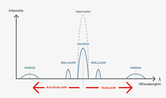
Following a specific monochromatic input pulse, the resulting backscattered light that comes backwards inside the fiber has the following profile (Figure 5):

Same wavelength—Rayleigh backscattering
Positive (Stoke) and negative (anti-Stoke) low shift—Brillouin backscattering
Positive (Stoke) and negative (anti-Stoke) high shift—Raman backscattering

Rayleigh backscattering

fiber_optic_sens_fig5

Figure 5: How Raleigh, Brillion and Raman backscattering occur

Rayleigh scattering is a phenomenon you experience nearly every day. It is the effect that makes the sky look blue (Figure 6).

Rayleigh scattering describes the elastic scattering of light by spheres which are much smaller than the wavelength of light. The most important discontinuity inducing Rayleigh backscattering into fiber optics results from small variations in the core refractive index. These discontinuities are, by construction, evenly distributed along the fiber and therefore induce a constant backscattering noise back to the source (Figure 7).

fiber_optic_sens_fig6

Figure 6: Raleigh scattering: why the sky is blue

Rayleigh backscattering is the technology an OTDR (optical time-domain reflectometer) relies on. Most fiber optic telecom technicians use it every day to test and troubleshoot fiber optic links. It adds a time domain calculation to the Raleigh backscattering effect, enabling the exact location of a failure on the line to be found using the time of flight (Figure 4).

Brillouin backscattering

fiber_optic_sens_fig7

Figure 7: Evenly distributed discontinuities induce constant backscattering.

Brillouin backscattering occurs due to the interaction between the light and acoustic phonons travelling in the fiber (caused by thermal excitation or strain). As the light is scattered by a moving entity (phonon), its frequency (wavelength) is shifted by the Relativistic Doppler effect (by around 10 GHz or 0.1 nm for a 1550 nm wavelength). Light is generated at both at positive (Stoke) and negative (anti-Stoke) shifts to the original optical wavelength (Figure 8). The intensity and frequency shifts of the two components are dependent on both temperature and strain. By measuring the shifts’ absolute values, the two parameters can be calculated. However, as both temperature and strain are convoluted in the measured value, Brillouin-based systems usually consist of two fibers: one is linked to the structure, measuring both strain and temperature, and the other one is free from the structure, measuring temperature only and being used as a temperature compensation for the strain measurement.

Raman backscattering

Raman scattering occurs when light is scattered due to interaction with molecular vibrations in the fiber. As with Brillouin scattering, positive (Stoke) and negative (anti-Stoke) shift components are produced and these are shifted from the wavelength of the incident light. By measuring the ratio in intensity between the Stoke and anti-Stoke components, an absolute value of temperature can be measured (Figure 9). Usually only the anti-Stoke component, which is the most temperature dependent, is monitored. Raman backscattering is exclusively temperature dependent, so only one fiber can be used (unlike Brillouin).

Interconnecting solutions
Fiber optic sensing technologies require top-of-the-range optical performances to work flawlessly (with a good signal-to-noise ratio). Insertion loss must be as low as possible and return loss is a critical concern, as the returning light contains information about the measurement. Optical connectors are generally specified in APC end faces for Single mode, as they guarantee the lowest possible return loss. Manufacturing a good and reliable APC termination requires top-of-the-range polishing equipment and skilled operators. Each termination must be certified in terms of end-face geometry to guarantee good physical contact (thus ensuring ultra-low return losses). On the connector construction stand point, each APC terminus has to be keyed properly and the shell must have been designed with fiber optic in mind, since the overall tolerances must meet the termini design requirements.

fiber_optic_sens_fig8

Figure 8: Brillouin backscattering generates light at positive and negative shifts to the original optical wavelength.

Sensing and instrumentation are by nature exposed to environmental constraints; the cable assemblies and connections that carry the measurement therefore have to be able to withstand these conditions. This can be challenging and requires premium materials and high-quality solutions. Having a strong, reliable, easy-to-maintain and quickly deployable fiber optic solution is the key to success.

Ease of maintenance is an important factor, as associated downtimes can lead to considerable loss of earnings when the sensing system is a critical part of the security loop associated with the main production.

fiber_optic_sens_fig9

Figure 9: By measuring the ratio in intensity between the Stoke and anti-Stoke components om Raman backscattering, an absolute value of temperature can be measured.

Fischer Connectors can provide premium, high performance, robust fiber optic cable assembly solutions that are designed for extreme environmental resistance and ease of use, due to its unique push-pull locking system and easy maintenance.

For example, its Fischer FiberOptic series offers a ready-to-use solution for field deployment. Its ruggedness ensures quick and safe connections, even when handled by untrained operators. Its extreme cleanability, coupled with its removable sleeve holder, enables a first level of maintenance even in the field. You can also obtain pre-terminated cable assemblies in single Mode APC and other fiber types, for perfect integration into sensing applications. The rugged and sealed bodies ensure a high degree of mechanical protection, while making no compromise on optical performance, thanks to their shell design and best-in-class butt joint termini. Available in 1, 2 and 4 fibers, the range features a wide choice of body styles to fulfill all your integration needs.
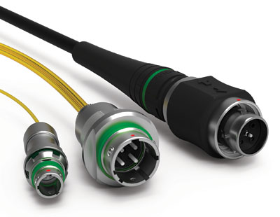
Fischer-FO1-fiber-optic-connectors-

Fischer’s FiberOptic Series single fiber optic connector (FO1)

In March 2016, Fischer Connectors launched its new single fiber optic connector (FO1) within its Fischer FiberOptic Series. This miniature, lightweight, rugged connectivity solution is easy to use and ensures premium performance even in harsh environments. The FO1 connector is also available either in pre-configured reels or integrated into custom assemblies for applications in instrumentation and sensing – to name only a few of the various fields for which this new product is ideally suited.

This new connector fulfills the growing market need for higher data transmission rates over long distances, while reducing space and guaranteeing performance by means of rugged miniature solutions.

Fischer Connectors
fischerconnectors.com


The post Fiber optic cabling solutions for sensing applications appeared first on EE World Online | A network of resources for engineers.

100G Lambda MSA releases specs for next-gen optical interconnects

$
0
0

The 100G Lambda Multi-Source Agreement (MSA) Group has announced the release of preliminary specifications based on 100 Gbps per wavelength PAM4 optical technology. Under the MSA, member companies addressed the technical challenges to achieving optical interfaces utilizing 100 Gbps per wavelength PAM4 technology, enabling multi-vendor interoperability for optical transceivers produced by different manufacturers and in various form factors. These new optical interface specifications target the next generation of networking equipment that is required to address the industry’s ever-growing demand for increased bandwidth and bandwidth density.

Lambda MSAThe 100G Lambda MSA Group Promoter members include: Alibaba, Applied OptoElectronics, Arista Networks, Broadcom, Ciena, Cisco, Finisar, Foxconn Interconnect Technology, Inphi, Intel, Juniper Networks, Lumentum, Luxtera, MACOM, MaxLinear, Microsoft, Molex, NeoPhotonics, Nokia, Oclaro, Semtech, Source Photonics, and Sumitomo Electric.

The new interfaces defined by the 100G Lambda MSA increase the distances supported for 100 GbE and 400 GbE applications compared to the 100 Gbps (100GBASE-DR) and 400 Gbps (400GBASE-DR4) 500-meter reach interfaces currently being defined by IEEE 802.3 Ethernet. The 100G Lambda MSA has developed optical specifications for 100 GbE with reaches of 2 and 10 kilometers and for 400 GbE with a reach of 2 kilometers over duplex single-mode fiber. By focusing on 100 Gbps per wavelength, the 100G Lambda MSA is enabling a technology ecosystem for next generation networking equipment.

The 100G Lambda MSA preliminary specifications are available for download at www.100GLambda.com. The MSA Group expects to complete the full specifications by early 2018. Companies are invited to join the consortium as Contributor members.

The post 100G Lambda MSA releases specs for next-gen optical interconnects appeared first on EE World Online | A network of resources for engineers.


High-speed millimeter-wave end launch connectors provide 1.10:1 VSWR

$
0
0

Fairview Microwave Inc. has released a new line of high-speed, mmWave end launch connectors. They are ideal for signal integrity measurements, chip evaluations, coplanar waveguide, 25 GbE, SERDES, substrate characterization and test fixture applications.

millimeter-wave end launch connectorsFairview’s new line of high-speed end launch connectors is comprised of 4 models that provide VSWR as low as 1.10:1 and a maximum operating frequency of 40 to 110 GHz, depending on the model. These connectors are reusable, don’t require any soldering and have a compact profile with a 0.350-in. mounting width and a 0.005-in. launch pin. They feature an outer conductor made of stainless steel and a gold-plated beryllium copper center contact. These end launch connectors are ideally suited for high-speed digital and mmWave system development.

“Our new family of end launch connectors delivers amazing VSWR performance with a reduced mounting profile, allowing our customers to fit even more connections in the same PCB area,” said Dan Birch, Product Manager at Fairview Microwave.

Fairview Microwave
www.fairviewmicrowave.com

The post High-speed millimeter-wave end launch connectors provide 1.10:1 VSWR appeared first on EE World Online | A network of resources for engineers.

CAMI Research launches CableEye HV-rated QuickMount housing for connector boards

$
0
0

CAMI Research Inc. has released a High-Voltage (HV)-rated QuickMount housing (CBH2) for its CableEye automation-ready, cable and wire harness testing systems. As a free-standing, quick-release board fixture, it allows users to connect CAMI’s test interface boards to the 64-pin headers of any expansion module — even at some distance. The housing may be used with any CableEye model and is rated to 2100 Vdc / 1500 Vac.

CAMI-Research-CableEye-HV-Rated-QuickMountA set of two boards, each CB26U accepts two USB Type-C connectors. In addition to the latest CableEye software, it requires the CB26 small-frame motherboard (Item 756) for operation, and plugs into one of two available slots – two USB-C-connectors can be tested simultaneously.

CAMI offers the CableEye suite of products complete with accessories — including plug-in connector boards. The selection of these test fixture boards is constantly growing and is currently numbering more than 60 — most of which are populated with families of connectors. When pre-populated boards are used, the tester GUI automatically displays a graphic of the connectors under test.

This free-standing board-fixture supports any CAMI connector board. Use this for connecting these boards to an expansion module, or for applications in which the connector boards must be separated from the tester. If desired, boards may be locked in place using supplied nylon thumbscrews. Choose a length of expansion cable to extend the housing away from the tester by the desired amount. For systems larger than 256 test points, use multiple QuickMount housings with increasingly longer expansion cables as shown in the photo (we will build to order). There are two types of expansion cable. For test voltages up to 500 V, we have ribbon cables (Item 856). For higher test voltages we offer optional Ampmodu cables (Item 864).

Available immediately, the CBH2 is $250 (Item 712H) and requires two expansion cables (Item 856 or Item 864 as appropriate for the test voltage and connection length) to connect to the tester: Two 50in. ribbon expansion cables are included. An optional add-on tilt stand (Item 712A) may be purchased for each housing. Connector boards are not included.

CAMI Research
www.camiresearch.com

The post CAMI Research launches CableEye HV-rated QuickMount housing for connector boards appeared first on EE World Online | A network of resources for engineers.

What are flat cables?

$
0
0

Flat cables allow for compact designs of electrical conductors and tubing, encasing power, signal, video, data and even pneumatic tubing in one flat profile. By eliminating the multiple layers of fillers, shielding and jacketing used in round cables, they offer reduced space and weight and extremely long lives.

Highly Complex Cables _opt

Flat cables, such as Cicoil’s Flexx-Sil designs, allow for compact, unique shapes.

Because of their smooth, compact design, flat cables are more flexible than their round counterparts, especially in high-flex applications such as robots, festoon and automated processing equipment. They are also suitable to military, aerospace, medical and clean room systems. This flexibility can be attributed to the fact that flat cables flex equally and in the same plane, reducing the twisting and stress put on round cables. Offering small bend radii, flat cables are able to fit into tight and compact spaces and are designed for up to tens of millions of cycles.

The conductors in flat cables are equally spaced, with the exact same distance to travel. In round cable, however, the wires twist and turn inside the cable, so the spacing and the length of travel varies, and it constantly changes. The result is that flat cables have significantly better electrical performance than round cables, including faster signal speeds, less skew, and higher current-carrying capacity, due to the consistent, straight-line path for the electrical current in a flat cable.

A final advantage of flat cable designs is that they are easier to terminate and identify than round cables because of their parallel conductor layout. This parallel design also means they are easy to repair, and this equality makes the design strong, as stress and loads are evenly distributed throughout the cable.

The post What are flat cables? appeared first on EE World Online | A network of resources for engineers.

TE Connectivity showcases computing and industry innovations at DesignCon 2018

$
0
0

TE Connectivity (TE) will showcase its Sliver interconnects at DesignCon 2018 that have been adopted as the SNIA SFF TWG Technology Affiliate’s SFF-TA-1002 specification multi-lane high speed connector. Multiple groups within the industry including the Consortium for On-Board Optics (COBO), the Gen-Z Consortium (Gen-Z), Open Compute Project (OCP) and Enterprise & Data Center SSD Working Group (EDSFF) have adopted TE’s Sliver internal cabled and card edge interconnects as the standardized connector solutions in their server, storage and networking designs. Sliver interconnects provide one of the most flexible, high-performance solutions in the market for making internal input/output (I/O) connections on the board.

TE-Sliver internal cabled interconnectsIn addition, Sliver interconnects simplify design and help lower overall costs by eliminating the need for re-timers and costlier, lower-loss printed circuit board (PCB) materials while reaching speeds greater than 50 gigabits per second (Gbps). Sliver interconnects are available as cable to board connections, card edge connections, with straddle mount and orthogonal additions in the works. Sliver is an ideal solution for many different applications, including high-speed I/O, optical connectivity, PCIe cabled extension, PCIe high-speed card edge, storage connectivity and general-purpose computing on graphics processing units (GPGPU) internal/external cabling.

COBO is developing a series of specifications to permit the use of embedded optical modules in the manufacturing of networked equipment (i.e. switches, servers, etc.). The organization references industry specifications where possible and develops specifications where required with attention to electrical interfaces, pin-outs, connectors, and thermals, to name a few, for the development of connectable, interchangeable and interoperable embedded optical modules that can be mounted onto motherboards and daughter cards.

“Sliver’s ability to deliver greater than 50 Gbps performance made it the ideal connector to standardize the high-speed data interface,” said Brad Booth, President of COBO. “Sliver interconnects are a critical component in COBO’s data center networking specification to facilitate the use of embedded optical modules in network equipment across multiple generations of Ethernet data rates.”

Gen-Z was developed to enhance existing and enable new solution architectures while delivering new levels of performance (high bandwidth, low latency), software efficiency, power optimizations and industry agility.

“Products like Sliver interconnects allow us to drive higher performance and greater flexibility in our designs,” said Kurtis Bowman, president of the Gen-Z Consortium. “TE Connectivity products are a key element to our scalable connector strategy and forthcoming specification release, helping our open standards forum achieve its technology goals.”

“At TE we aim to support our customers through products that are higher performing and have greater flexibility,” said Barbara Grzegorzewska, Director of Product Management, I/O TE Connectivity. “Sliver interconnects excel in providing these benefits, and we are very pleased that the SFF-TA-1002 standard has named it as the connector of choice.”

Visit TE at DesignCon 2018, booth #817 to see a live demo of Sliver interconnects.

TE Connectivity
www.TE.com/sliver

The post TE Connectivity showcases computing and industry innovations at DesignCon 2018 appeared first on EE World Online | A network of resources for engineers.

PCB Piezotronics launches University Laboratory Programs

$
0
0

PCB-Piezotronics-logoPCB Piezotronics Inc. announces the launch of its University Laboratory Programs. These Programs provide significant cost savings for acoustics, civil engineering, mechanical engineering, and physics curricula that incorporate hands-on student labs. Each program bundles sensors and accessories, laboratory experiments, classroom lecture, and technical poster for use in academic classrooms and laboratories.

With a history of providing discounted sensors to the academic community, PCB is expanding its commitment with four new Laboratory Programs that help both seasoned and first-time instructors provide comprehensive educational programs for their engineering classes. Students will have hands-on experience with state-of-the-art sensors used by today’s research and development facilities throughout the world.

Each Laboratory Program includes:

  • Discipline-specific kits with the most commonly used sensors (acoustics, vibration, force) and accessories
  • Instructor’s Guide of laboratory experiments with step-by-step instructions
  • Technical poster for display in laboratories
  • A classroom lecture by a PCB expert

These Programs are simple to order and use, and available at a substantial discount to meet tight academic budgets. Recommended optional products are also discounted. Additional engineering and technical disciplines will be added in the near future.

PCB Piezotronics
www.pcb.com/university

The post PCB Piezotronics launches University Laboratory Programs appeared first on EE World Online | A network of resources for engineers.

Newark element14 adds product configurator from Samtec

$
0
0

Newark element14 has added a new Product Configurator from Samtec. The configurator allows customers to modify any Samtec Connector to obtain a variation which is exactly suited for their application. The new online tool enables customers to modify connectors and download 2D and 3D models in just minutes.

product configuratorAs each parameter within the tool is modified, the resulting 3D image can be refreshed within the page and any changes will display a unique manufacturer part number that will capture the selected parameters.

This tool, which is being launched in North America and the UK, gives access to a variety of connector variations from Samtec. As the modified product is not custom designed, and is a standard Samtec modification, customers taking advantage of this new tool would not experience long lead times or “custom” prices. Once the product is adjusted, the final version of the product can be downloaded in 150 potential file formats including STEP, SolidWorks, Autodesk and a png or PDF file.

According to Chris Swetman, Head of Technical Product Data Experience for Premier Farnell and Newark element14, “As the Development Distributor, we are always seeking new ways to help our customers design their products and accelerate their time to market. By partnering with Samtec we are creating a richer customer experience and are able to offer an extensive range of connector products along with productive tools, such as the Product Configurator, which reduce design hours and helps our customers prototype their product more quickly and efficiently.”

Ashley Quinlan, Strategic Marketing Director at Samtec, added, “We’re excited to partner with Newark elemment14 in bringing Samtec’s design flexibility to all of their customers. This capability spans all interconnect segments, including 28 Gbps NRZ/56 Gbps PAM4 solutions, miniaturized products, rugged, arrays, edge cards, industry standard, and board stacking solutions. The Configurator tool allows the customer to quickly modify the pin count, lead style, plating, packaging, and much more to obtain the ideal solution for their application, and immediately download a model of the configured part in the format of their choice. Should a customer configure a part that Newark element14 does not stock, the part can be drop shipped to the customer in less than a week in most cases.”

The Samtec Configurator is now available to use on Newark element14 in North America and Farnell element14 in the UK.

It can be found within transactional pages by clicking the “modify this part” icon.

Newark element14
www.newark.com/samtec

The post Newark element14 adds product configurator from Samtec appeared first on EE World Online | A network of resources for engineers.

Series of tall board-to-board stacker connectors for demanding applications

$
0
0

AVX Corp. has released a new series of tall board-to-board stacker connectors. The new 00-9148 Series tall stacker connectors are cost-effective, reliable, and robust; exhibit excellent resistance to shock and vibration; and help reduce tolerance accumulation in a variety of demanding applications across the automotive, consumer, medical, and industrial markets.

board-to-board stacker connectorsThe single-piece connectors also reduce assembly time and shorten BOM lists, and feature a double-row design with an 8 mm (±0.2 mm) board-stacking height, a 1 mm pitch, and eight positions, each rated for 1 A continuous current. Additionally, due to flexible tooling, application-specific variants, including: single-row connectors with 4–16 positions, double-row connectors with 8–32 positions, connectors with 4–12mm board-stacking heights, and connectors with locating bosses for enhanced mechanical stability — all with the same fine 1mm contact pitch — can also be accommodated. Rated for 125 V, 50 cycles, and temperatures spanning –40° to 125°C, 00-9148 series connectors are ideal for connecting two parallel boards in applications including: automotive entertainment systems, portable devices that require docking or cradle charging, patient monitoring devices, portable medical equipment, industrial devices that require pluggable or programmable modules, and internet applications that require battery back-up, amongst others.

The new 00-9148 Series tall stacker connectors feature high-temperature plastic insulators that meet the UL94 V-0 flammability standard, high-reliability beryllium copper (BeCu) contacts with 0.25 μm standard gold plating on the nose, or 0.8 μm upon request, and pure-tin over nickel SMT terminations compatible with RoHS-compliant, lead-free reflow soldering processes. The series is supplied in tape and reel packaging in quantities of 400 pieces and mates with gold-plated pads on mating board surfaces.


AVX Corp.
www.avx.com

The post Series of tall board-to-board stacker connectors for demanding applications appeared first on EE World Online | A network of resources for engineers.


Carlisle Interconnect Technologies demonstrates CoreHC and card edge connectors at DesignCon 2018

$
0
0

CarlisleIT, a division of Carlisle Companies is introducing an updated CoreHC interconnect solution and brand-new Card Edge Connectors contact system as part of its integrated line of high-performance microwave cables and psrecision RF and high-speed digital connectors for Test & Measurement applications at DesignCon 2018 Expo in Santa Clara, Calif., this week in booth #648.

CarlisleIT’s CoreHC interconnect solution direct attach cable assembly is a multi-channel, test point system targeted for high-density boards where space is limited. It offers reduced trace lengths and higher signal integrity compared to boards using traditional SMA-type connectors. On average, there is four times higher available bandwidth for signals in the same real estate as SMA connectors. This latest version of the CoreHC interconnect solution is now a solderless, one-piece interface for PCB vertical and edge launch in a small footprint, which will save time and reduce overall costs because no soldering to the board is required. It is also designed for high-cycle capability without sacrificing signal integrity.

The Card Edge Connectors contact system is designed for high-speed, high-density applications. It has a smooth mating surface area, which reduces the wear and tear of contacts and increases the durability and cycle life of the contact system. It saves space and cost with a contact pitch of 0.8 mm, minimized stub length and integral ground blade for high performance. It also lowers insertion and withdrawal forces while supporting data rates up to 25GHz with excellent signal integrity.

CarlisleIT
www.carlisleit.com

The post Carlisle Interconnect Technologies demonstrates CoreHC and card edge connectors at DesignCon 2018 appeared first on EE World Online | A network of resources for engineers.

Molex spotlights high-speed data connectivity at Designcon 2018

$
0
0

Molex is showcasing its high-speed data connectivity solutions at DesignCon 2018 in Santa Clara, Calif., this week. In its booth 633, the company will feature next-generation technologies designed to meet rising data speeds and bandwidth in demanding networking and high-performance computing applications.

“As more data is generated and infrastructure moves to the cloud, next-generation I/O and cabling solutions support faster processing, more bandwidth, increased density and thermal management—while maximizing data flow efficiency and reliability in today’s data centers,” said Jairo Guerrero, general manager of enterprise solutions, Molex.

At DesignCon 2018, Molex will display the following demos:

  • Impulse Orthogonal Direct Backplane Connector System delivers improved performance, class-leading density and cost savings by eliminating the need to build and install midplane connections. Designed for high-density data center applications, the new Impulse backplane system supports data rates of 56 and 112 Gbps PAM-4 with superior signal integrity.
  • The Quad Small Form Factor Pluggable Double Density (QSFP-DD) System for high-density, high-speed networking will showcase how the eight-lane electrical interface operates up to 25 Gbps NRZ modulation or 56 Gbps PAM-4, with feasibility of 112 Gbps PAM-4, in support of the growth in future bandwidth needs.
  • Mirror Mezz Connectors highlight flexibility with stackable mating to support data speeds up to 56 Gbps NRZ and 112 Gbps PAM-4 per differential pair. These hermaphroditic connectors are highly compact and designed to provide ease in PCB routing in any direction out of the connector interface.
  • Molex-NearStack_2

    Molex’s NearStack high-speed connector system and cable jumper assemblies

    NearStack High-Speed Connector System and Cable Jumper Assemblies use twinax cables to deliver a PCB alternative with superior signal integrity and low insertion loss while enabling implementation of 56 Gbps NRZ and a path to 112 Gbps PAM-4.

  • Impel Plus Cabling System showcases its backbone functionality within the Open19 Project which defines a common form factor for servers, Tier0 switches, and power shelves with a base internal cage system that can be implemented into a standard 19” rack solution. Delivering lower costs and reliable signal integrity from the switch to server with a robust connector to cable interface, the Molex Impel Plus Cabling System achieves data rates up to 50 Gbps PAM-4 to create 100 Gbps connectivity per server with the Open19 solution.

Molex will highlight its high-density blind-mating optical backplane connectors for card, sled and drawer applications that incorporate multi-fiber MT and VersaBeam expanded beam MT ferrule technology enabling the deployment of optical I/O based hardware. By utilizing Molex FlexPlane and Routed Ribbon Solutions, system architects are able to manage on board optical fiber counts that range from hundreds to thousands of fibers.

Combining passive, high-speed copper twinax cables with NearStack and QSFP+ or QSFP-DD connectors, BiPass I/O and Backplane Cable Assemblies provide a low-insertion-loss alternative to PCB traces for high bandwidth speeds, efficiency and proper thermal management. The integrated, one-piece BiPass cable assembly ensures easy installation in data switching, IP networking and telecom communications for 56 Gbps PAM-4 and a path to 112 Gbps PAM-4 applications.

Interconnect Systems International (ISI) will display their advanced packaging and interconnect solutions using a multi-discipline customized approach to improve solution performance, reduce package size and expedite time-to-market for customers.

The newly expanded zSFP+ Interconnect System that supports 56 Gbps PAM-4 channels in stacked 2xN port configurations, will showcase how next-generation Ethernet and Fibre Channel applications receive standout signal integrity. The system allows for users to merge standard cables and modules with the increased data-rate accepted.

Additionally, Molex will join other industry experts in two technical sessions at DesignCon 2018:

  • 10-10:45 am, Wednesday, January 31:  112G Electrical System Performance Study — Based on an Improved Salz SNR Methodology. The technical session will explore an early system design stage for 112G when no silicon nor hardware components are available, an improved Salz SNR analytical model is derived and a methodology for assessing system margin is introduced. Unlike traditional ICR based Salz method, major noise terms that are recognized to be dominant and are weighted much higher in PAM-4 than in NRZ systems are included. Performance ‘upper limits’ such as maximal tolerable insertion loss and crosstalk for ‘optimal’ modulation scheme is analyzed for six backplane architectures and those with higher possibility to meet the ‘upper limits’ are selected for full channel modeling and margin analysis. Molex experts will discuss how channel architectures are using most up-to-date Molex Backplane family of connectors such as Impulse Orthogonal Direct connectors and Impulse backplane cables as well as BiPass cable assemblies with near-ASIC connector family to solve design challenges.
  • 2:50-3:30pm, Wednesday, January 31: Fast Resonance Reduction Using Eigenmode Solution and Custom Metrics. The technical presentation will focus on the presence of resonant frequencies in electromechanical devices as one of the primary issues that inhibits the quality of high-speed data transmission. Signal integrity engineers typically spend a significant portion of the design process on finding and suppressing resonances; this is primarily due to the iterative nature and computational expense of using conventional frequency-domain solvers. Molex experts will discuss an alternative design approach and methods used to quickly identifying resonances in multi-ground connector and circuit board structures.

Molex
www.connector.com/solutions/designcon

The post Molex spotlights high-speed data connectivity at Designcon 2018 appeared first on EE World Online | A network of resources for engineers.

TE Connectivty and Credo demonstrate 112G single-lane connectivity at DesignCon 2018

$
0
0

TE Connectivity (TE) and Credo, provider of high performance, mixed-signal semiconductor solutions for the data center, enterprise networking and high-performance computing markets, today announced they have teamed up to demonstrate the future of networking technologies. The companies will hold demonstrations of 112Gbps over a chip-to-module (IO) channel and over a backplane channel at DesignCon 2018. The demonstrations will be unveiled at booth #817 at DesignCon, which takes place in the Santa Clara, Calif. convention center from through tomorrow, February 1. As industry groups such as OIF and IEEE meet to discuss feasibility of these types of links at these next-generation data rates, TE and Credo will be demonstrating performance on actual hardware.

The IO channel demonstration uses TE’s OSFP IO connector with Credo’s 16nm, lower power, high performance 112G PAM4 SerDes technology to exhibit operation over a 10-in. printed circuit board (PCB) channel. The “O” is for “octal” — it is being designed to use eight electrical lanes to deliver 400GbE — and “SFP” is for “small form factor pluggable.” The channel is driven by Credo’s 112G PAM4 SerDes, which is operating over a total ball-to-ball channel loss of >15 decibel (dB). The demo shows bit error rate (BER) performance of better than 1e-7. The OSFP IO connector is a state-of-the-art 8 channel IO connector currently adopted for 400Gbps applications. The demonstration establishes TE’s OSFP connector performance as an 800Gbps-capable IO solution.

The backplane demonstration uses TE’s latest STRADA Whisper orthogonal backplane connector operating with a total channel loss of 20 dB at 28 GHz in a PCB-based direct plug orthogonal (DPO) architecture. Driven by Credo’s 112G PAM4 SerDes, the demo shows BER performance levels that fully enable the adoption of STRADA Whisper solutions for the next wave of networking equipment.

“Credo’s proven low power silicon expertise being advanced to 112G SerDes is a key technology milestone. Credo is enabling the industry to progress quickly to 112Gbps serial electrical signaling, which may pave the way for accelerating the deployment of 112G single lane, end-to-end network connectivity. Enabling faster data, in smaller spaces at a potentially lower cost,” said TE’s Nathan Tracy, technologist, member of system architecture team and industry standards manager.

“TE’s OSFP IO connector demonstrates the extremely low noise performance that will be required in 112Gbps IO applications. In addition, the performance of TE’s latest STRADA Whisper backplane connector enables the balance of the 112Gbps signaling interconnect ecosystem. TE’s world-class interconnect performance has demonstrated that it is 112Gbps ready,” said Jeff Twombly, vice president of business development at Credo.

TE Connectivity Ltd.
www.te.com

Credo Semiconductor
www.credosemi.com

The post TE Connectivty and Credo demonstrate 112G single-lane connectivity at DesignCon 2018 appeared first on EE World Online | A network of resources for engineers.

TE Connectivity highlights 400Gbe OSFP and QSFP-DD connectivity at DesignCon 2018

$
0
0

TE Connectivity (TE) today announced the showcasing of OSFP and QSFP-DD connectivity products at this year’s DesignCon show that will soon enable 400-Gigabit Ethernet in a range of data center devices. TE is demonstrating the new products in booth 817 at the DesignCon 2018 expo through tomorrow, February 1 in Santa Clara, Calif.

Targeted for massive aggregation of data across an array of applications, 400 Gigabit Ethernet (GbE) has completed the standardization process and was published in December 2017 by the IEEE 802.3bs Ethernet Working Group. Development of new and faster electrical and optical signaling technologies is simultaneously underway across the ever-expanding Ethernet ecosystem.

The QSFP form factor is today’s industry workhorse for delivering 40 and 100GbE. The “Q” is for “quad” — a nod to the four-channel electrical interface, with each lane running at 25 Gbps for 100GbE. TE’s QSFP-DD connector adopts the same basic concept as its predecessor, but doubles the electrical contact density, via eight differential pairs capable of 50 Gbps each, to achieve 400GbE while allowing existing QSFP modules to be plugged into the same cage.

The OSFP form factor is designed for maximum thermal and electrical performance, but does not provide backwards compatibility to existing form factors without an adapter. The “O” is for “octal” — it is being designed to use eight electrical lanes to deliver 400GbE — and “SFP” is for “small form factor pluggable.

“At TE, we are focused on delivering products that make our world smater, faster and more connected. Our OSFP and QSFP-DD products bring data center equipment into the 400GbE age,” said Nathan Tracy, technologist for TE’s system architecture team and manager of industry standards. “By giving customers a choice between fully-optimized thermal performance and backward compatibility with existing QSFP connectors, we support the complete range of 400GbE solutions for system designers.”

TE Connectivity Ltd.
www.te.com

The post TE Connectivity highlights 400Gbe OSFP and QSFP-DD connectivity at DesignCon 2018 appeared first on EE World Online | A network of resources for engineers.

Cat 6A RJ-45 connectors from WAGO for industrial applications

$
0
0

Wago-RJ45-1200x1200New Cat 6A RJ-45 connectors from WAGO feature a metal housing that helps provide rugged connections for industrial applications. These economical connectors have 360° shielding for added EMC protection against electrical noise and interference.

Industrial grade RJ-45 connectors are available for ETHERNET and PROFINET fieldbus protocols in a variety of configuration options: straight with or without strain relief and right angle with strain relief. Wiring is fast and intuitive with pre-labeled terminations and insulation displacement connectors.

WAGO
www.wago.us

The post Cat 6A RJ-45 connectors from WAGO for industrial applications appeared first on EE World Online | A network of resources for engineers.

Viewing all 466 articles
Browse latest View live


Latest Images